Introduction adder alu 4-bit serial adder/subtractor with parallel load Adder serial fsm mealy circuit state table type using moore vhdl fig assigned
Serial Adder using Mealy and Moore FSM in VHDL – Buzztech
Diagrams circuit adder What is half adder and full adder circuit? Adder circuit logic schematic circuitglobe circuits sum fig compressor robhosking combinational shown
Binary adder and parallel adder
Adder serial bit subtractor parallel load shift flop flip carry four simplified schematics registers right twoSerial adder using mealy and moore fsm in vhdl – buzztech Design of a serial binary adderAdder serial flip flop parallel binary flipflop use clock electronics stack taken.
Circuit diagramsAdder serial binary Serial adder diagram bit twoSerial adder.

SERIAL ADDER - ELECTRICAL ENCYCLOPEDIA

1 Introduction

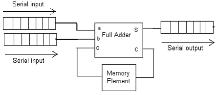
Design of a Serial Binary Adder

Serial Adder using Mealy and Moore FSM in VHDL – Buzztech

Circuit Diagrams

What is Half Adder and Full Adder Circuit? - Circuit Diagram & Truth

Binary Adder and Parallel Adder - Electrical Engineering Stack Exchange